1. Introduction
The Unbound.io single-wire CAN (SW-CAN) extension board is a Raspberry Pi compatible interface board intended to add one or two SW-CAN channels to a Raspberry Pi through SPI-connected CAN controller interfaces.
The board is designed to support the following configurations:
- One-channel configuration: one SPI interface, one SW-CAN channel.
- Two-channel configuration: one or two SPI interfaces, two independently selected SW-CAN channels.
- Flexible routing: the onboard switches and jumpers select the SPI bus, SPI chip-select, and interrupt GPIO assigned to each channel.
- Linux SocketCAN integration: when the MCP2515-compatible controller and
transceiver are correctly configured, Linux exposes the channels as
can0,can1, or another SocketCAN interface name selected by the kernel.
The board follows the Raspberry Pi 40-pin HAT-style electrical interface. It is not a Raspberry Pi computer by itself; a compatible Raspberry Pi, suitable power supply, enabled SPI controller, and correctly configured Device Tree Overlay are required.
1.1 Important terminology
| Term | Meaning |
|---|---|
| SW-CAN | Single-wire CAN physical-layer interface used by the target vehicle/network. |
| MCP2515 | SPI CAN 2.0B controller used by the referenced Raspberry Pi overlay configuration. |
| SPI | Serial Peripheral Interface used between the Raspberry Pi and CAN controller. |
| CS / CE | SPI chip-select signal. CS0 and CS1 correspond to SPI chip-select lines. |
| INT | CAN controller interrupt output connected to a Raspberry Pi GPIO. |
| SocketCAN | Linux CAN networking interface used by ip, candump, and cansend. |
2. Hardware connection introduction
2.1 Raspberry Pi 40-pin connector
The following table uses the BCM GPIO numbering and signal names specified by the Waveshare 2-CH CAN HAT MCP2515 interface reference. Physical pin numbers are included for wiring verification.
| Physical pin | BCM GPIO / function | Board signal | Description |
|---|---|---|---|
| 1 | 3V3 | 3V3 | 3.3 V supply/reference. |
| 2 | 5V | 5V | 5 V power input. |
| 3 | GPIO 2 / SDA1 | — | I2C SDA; not used by the MCP2515 SPI interface. |
| 4 | 5V | 5V | 5 V power input. |
| 5 | GPIO 3 / SCL1 | — | I2C SCL; not used by the MCP2515 SPI interface. |
| 6 | GND | GND | Ground. |
| 7 | GPIO 4 | — | General-purpose GPIO; not the default CAN interrupt in the Waveshare mapping. |
| 8 | GPIO 14 / TXD0 | — | UART TX. |
| 9 | GND | GND | Ground. |
| 10 | GPIO 15 / RXD0 | — | UART RX. |
| 11 | GPIO 17 | — | General-purpose GPIO. |
| 12 | GPIO 18 / PCM_CLK | — | Alternate-function GPIO. |
| 13 | GPIO 27 | — | General-purpose GPIO; board photo labels D13 as an INT0 option. |
| 14 | GND | GND | Ground. |
| 15 | GPIO 22 | — | General-purpose GPIO; board photo labels D22 as an INT1 option. |
| 16 | GPIO 23 | INT0 | CAN0 interrupt, default Waveshare mapping. |
| 17 | 3V3 | 3V3 | 3.3 V supply/reference. |
| 18 | GPIO 24 | — | General-purpose GPIO; possible INT1 alternative in the Waveshare reference. |
| 19 | GPIO 10 / SPI0 MOSI | MOSI | SPI controller-to-board data. |
| 20 | GND | GND | Ground. |
| 21 | GPIO 9 / SPI0 MISO | MISO | Board-to-controller SPI data. |
| 22 | GPIO 25 | INT1 | CAN1 interrupt, default Waveshare mapping. |
| 23 | GPIO 11 / SPI0 SCLK | SCK | SPI clock. |
| 24 | GPIO 8 / SPI0 CE0 | CS0 | SPI0 chip-select 0; CAN0 chip select in the standard mapping. |
| 25 | GND | GND | Ground. |
| 26 | GPIO 7 / SPI0 CE1 | CS1 | SPI0 chip-select 1; CAN1 chip select in the standard mapping. |
| 27 | GPIO 0 / ID_SD | — | HAT identification I2C SDA. |
| 28 | GPIO 1 / ID_SC | — | HAT identification I2C SCL. |
| 29 | GPIO 5 | — | General-purpose GPIO. |
| 30 | GND | GND | Ground. |
| 31 | GPIO 6 | — | General-purpose GPIO. |
| 32 | GPIO 12 | — | PWM/general-purpose GPIO. |
| 33 | GPIO 13 | — | PWM/general-purpose GPIO; board photo labels D13 as an INT0 option. |
| 34 | GND | GND | Ground. |
| 35 | GPIO 19 | — | PCM/frame signal alternate function. |
| 36 | GPIO 16 | — | General-purpose GPIO. |
| 37 | GPIO 26 | — | General-purpose GPIO. |
| 38 | GPIO 20 | — | PCM data alternate function. |
| 39 | GND | GND | Ground. |
| 40 | GPIO 21 | — | PCM data alternate function. |
Standard MCP2515 signals from the Waveshare reference:
| Board signal | Raspberry Pi BCM GPIO | Physical pin | Default use |
|---|---|---|---|
| MISO | GPIO 9 | 21 | SPI data from controller. |
| MOSI | GPIO 10 | 19 | SPI data to controller. |
| SCK | GPIO 11 | 23 | SPI clock. |
| CS0 | GPIO 8 / CE0 | 24 | CAN0 chip select. |
| INT0 | GPIO 23 | 16 | CAN0 interrupt. |
| CS1 | GPIO 7 / CE1 | 26 | CAN1 chip select. |
| INT1 | GPIO 25 | 22 | CAN1 interrupt. |
| 5V | 5V | 2 or 4 | Board power. |
| GND | GND | 6, 9, 14, 20, 25, 30, 34, or 39 | Ground. |
2.2 SW-CAN field connection
Connect the board SW-CAN channel to the target network according to the vehicle or network wiring specification. Verify the required signal names, signal return/ground, termination, and transceiver operating mode before applying power. Do not assume that an SW-CAN line can be wired like a two-wire high-speed CAN bus.
3. Hardware switch and jumper configuration
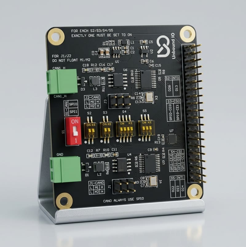
3.1 Configuration rules visible on the board
The board photograph contains the instruction:
For each of S2, S3, S4, and S5, set exactly one selector position to
ON. Never enable two positions in the same selector because this can connect
multiple signal sources together.
The ON direction is marked on the switch body. The board must be powered off
while changing switches or jumpers.
3.2 Switch functions extracted from the board photograph
| Selector | Signal controlled | Visible choices on the board | Function |
|---|---|---|---|
| S1 | Board-specific single switch | Red one-position switch; no complete function legend is visible in the supplied photograph | Use only according to the product schematic or confirmed board revision. Do not infer its function from the switch color. |
| S2 | INT0 | D25, D13 | Selects the GPIO routed to SW-CAN channel 0 interrupt. |
| S3 | CS0 | SPI0-CE0, SPI0-CE1 | Selects the SPI chip-select routed to SW-CAN channel 0. |
| S4 | CS1 | Four positions labelled with SPI chip-select alternatives on the silkscreen | Selects the SPI bus/chip-select route for SW-CAN channel 1. Use only one position. |
| S5 | INT1 | D22, D23, D24 | Selects the GPIO routed to SW-CAN channel 1 interrupt. |
The photograph is not sufficiently high-resolution to guarantee the exact
left-to-right text of every S4 position. Read the silkscreen on the physical
board and select the position that matches the intended SPIx-CEy route.
3.3 J1 and J2 jumper headers
The supplied photograph identifies the jumper headers as follows:
| Jumper | Silkscreen | Channel |
|---|---|---|
| J1 | J1-CAN0 with positions L, M, H | SW-CAN channel 0 |
| J2 | J2-CAN1 with positions L, M, H | SW-CAN channel 1 |
J1 and J2 are channel-specific routing/configuration jumpers. They are
used together with S2–S5 to select the SPI channel, interrupt routing, and
chip-select routing. The supplied photograph does not provide enough
information to assign an unambiguous electrical meaning to L, M, and H.
Therefore:
- Use the board schematic or the documentation supplied with the exact
Unbound.io board revision to identify the meaning of
L,M, andH. - Install one jumper cap only in the documented position for each channel.
- Do not short two positions together unless the schematic explicitly requires it.
- Power off the Raspberry Pi before changing
J1orJ2.
3.4 Recommended initial configuration
For a Raspberry Pi using the standard Waveshare MCP2515 mapping, begin with the following logical assignment:
| Channel | SPI route | Chip select | Interrupt |
|---|---|---|---|
| CAN0 | SPI0 | CE0 / GPIO 8 | GPIO 23 |
| CAN1 | SPI0 | CE1 / GPIO 7 | GPIO 25 |
Then configure the physical selectors so that the board actually routes those signals. If the board is configured for alternate interrupt GPIOs or SPI1, the Device Tree Overlay values must be changed to match.
4. Software configuration
4.1 Operating-system prerequisites
This section follows the Raspberry Pi MCP2515 procedure in the Waveshare 2-CH CAN HAT reference:
https://www.waveshare.net/wiki/2-CH_CAN_HAT
Install the CAN utilities and ensure the kernel contains SocketCAN and the MCP2515 driver:
sudo apt update
sudo apt install -y can-utils
Enable SPI using raspi-config, or verify that SPI is enabled in the boot
configuration:
sudo raspi-config
Select Interface Options -> SPI -> Enable, then reboot if requested.
4.2 Raspberry Pi Device Tree Overlay
For Raspberry Pi OS with Bookworm/Trixie or Ubuntu, the configuration file is normally:
/boot/firmware/config.txt
On older Raspberry Pi OS installations it may be:
/boot/config.txt
Back up the file before editing:
sudo cp /boot/firmware/config.txt /boot/firmware/config.txt.bak
sudo nano /boot/firmware/config.txt
For the standard two-channel MCP2515 mapping shown by Waveshare, append:
dtparam=spi=on
dtoverlay=mcp2515-can1,oscillator=16000000,interrupt=25
dtoverlay=mcp2515-can0,oscillator=16000000,interrupt=23
dtoverlay=spi-bcm2835-overlay
This example assumes:
- the MCP2515 oscillator is 16 MHz;
- CAN0 uses
SPI0 CE0and GPIO 23 forINT0; - CAN1 uses
SPI0 CE1and GPIO 25 forINT1; - the board switches and jumpers are configured to the same routing.
If the actual board oscillator is not 16 MHz, replace 16000000 with the
measured or schematic-specified oscillator frequency. A wrong oscillator value
causes incorrect CAN timing.
For a one-channel configuration, enable only the controller that is physically connected and routed, for example:
dtparam=spi=on
dtoverlay=mcp2515-can0,oscillator=16000000,interrupt=23
dtoverlay=spi-bcm2835-overlay
If INT0, INT1, CS0, or CS1 is changed using the board selectors, the
overlay must be changed to match the selected GPIO/bus/chip-select. The overlay
and hardware must never describe different connections.
Reboot after saving:
sudo reboot
Verify initialization:
dmesg | grep -Ei 'spi|mcp2515|can'
ls /sys/class/net
ip -details link show
4.3 Bring up a SocketCAN interface
Set the CAN bitrate according to the network specification. The following uses 1 Mbit/s, matching the Waveshare example:
sudo ip link set can0 down 2>/dev/null || true
sudo ip link set can0 type can bitrate 1000000
sudo ip link set can0 up

sudo ip link set can1 down 2>/dev/null || true
sudo ip link set can1 type can bitrate 1000000
sudo ip link set can1 up
Check the result:
ip -details link show can0
ip -details link show can1
4.4 Linux SocketCAN send and receive example
Install can-utils if it is not already installed:
sudo apt install -y can-utils
In terminal 1, receive on CAN0:
candump can0
In terminal 2, send an 11-bit CAN data frame on CAN1:
cansend can1 000#11.22.33.44
For a single-board bench test, connect the two SW-CAN channels only as permitted by the board and network design, and use a suitable test network. Do not connect the board directly to an unknown vehicle bus during initial software validation.
Stop the interfaces with:
sudo ip link set can0 down
sudo ip link set can1 down
5. Testing standards
The product is tested according to the LGM SW-CAN standard specified for the intended application. The applicable released LGM test specification, revision, and test limits shall be recorded in the project quality record.
The test program should cover, at minimum:
- correct Raspberry Pi 40-pin electrical connection;
- SPI communication and MCP2515 register identification;
- correct chip-select and interrupt routing for each enabled channel;
- SW-CAN transmit and receive operation at the required network bit rates;
- CAN error handling and recovery;
- power-up, reset, and repeated initialization;
- physical-layer signal integrity, polarity, and termination as required by the LGM SW-CAN standard;
- operation of one-channel and two-channel configurations;
- verification that unused selector positions do not create signal contention.
The statement “tested according to LGM SW-CAN standard” is a product test claim, not a substitute for the controlled LGM standard document. Use the current approved LGM revision and retain the test results, equipment calibration records, wiring configuration, switch settings, and software version.
References
- Waveshare, 2-CH CAN HAT, Raspberry Pi 40-pin interface, MCP2515 overlay, and SocketCAN examples: https://www.waveshare.net/wiki/2-CH_CAN_HAT
- Waveshare English reference: https://www.waveshare.com/wiki/2-CH_CAN_HAT
- Linux SocketCAN documentation: https://www.kernel.org/doc/Documentation/networking/can.txt
Revision history
| Version | Date | Description |
|---|---|---|
| 1.0 | 2026-08-02 | Initial user reference based on the supplied board photograph and Waveshare MCP2515 interface reference. |